RCL Ladder Network (DAE)
Description
This benchmark creates linear, time-invariant pH-DAE models for simple electric circuits consisting of ideal voltage sources, resistors, inductors and capacitors. The modelling of such circuits is described in [4].
Modeling of such electric circuits with directed graphs leads to systems of the following form:
\[\begin{aligned} E \dot{x}(t) &= (J-R)x(t) + Gu(t), \\ y(t) &= G^\mathsf{T} x(t), \end{aligned}\]
where
\[\begin{equation*} E = \begin{bmatrix} \mathcal{A}_c C \mathcal{A}_c^\mathsf{T} & 0 & 0 \\ 0 & L & 0 \\ 0 & 0 & 0 \end{bmatrix}, \, J = \begin{bmatrix} 0 & -\mathcal{A}_l & -\mathcal{A}_v \\ \mathcal{A}_l^\mathsf{T} & 0 & 0 \\ \mathcal{A}_v^\mathsf{T} & 0 & 0 \end{bmatrix},\, R = \begin{bmatrix} \mathcal{A}_r R^{-1}\mathcal{A}_r^{\mathsf{T}} & 0 & 0 \\ 0 & 0 & 0 \\ 0 & 0 & 0 \end{bmatrix},\, G = \begin{bmatrix} 0 \\ 0 \\ -I_m \end{bmatrix}. \end{equation*}\]
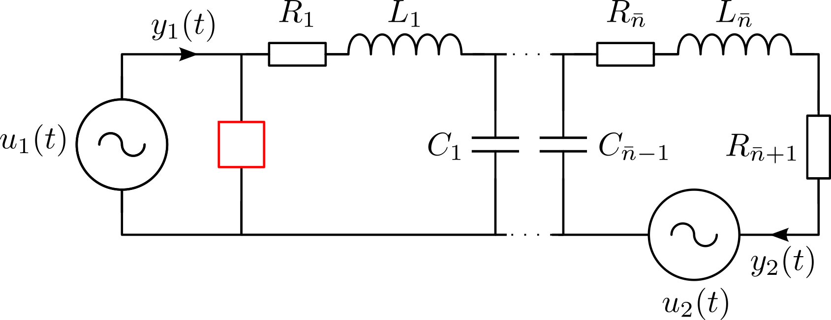
Here, the matrices $R,\,L,\,C$ are positive definite diagonal matrices that contain the resistances, inductances and capacitances, respectively, as entries. The incidence matrices $\mathcal{A}_r,\,\mathcal{A}_l,\,\mathcal{A}_c,\,\mathcal{A}_v$ follow directly from the directed graph of the network and contain only entries in $\{-1,0,1\}$. The inputs $u(t)$ of the system are the voltages $v_v(t)$ provided by the voltage sources and the outputs are the negative currents $i_v(t)$ through the voltage sources. The state vector is given by $x(t) := \begin{bmatrix} v(t)^\mathsf{T} & i_l(t)^\mathsf{T} & i_v(t)^\mathsf{T} \end{bmatrix}^\mathsf{T}$ with node voltages $v(t)$ and inductor currents $i_l(t)$. Consequently, the dimension of the model is given by $n = 3\widetilde{n} + 2m$, where $\widetilde{n}$ denotes the number of loops in the system and $m$ is the number of voltage sources. Since $\mathcal{A}_c C \mathcal{A}_c^\mathsf{T}$ is diagonal for the circuit in Figure 1, a transformation of the model to semi-explicit form is straightforward. The benchmark allows for different configurations of the network that will change the index of the resulting pH-DAE model and its number of inputs and outputs.
- SISO/MIMO: In the multiple-input multiple-output (MIMO) version, the inputs are the voltages of both voltage sources and the outputs are the currents as shown in Figure 1. In the single-input single-output (SISO) configuration, we replace the second voltage source by a wire and only consider the input-to-output behaviour from $u_1(\cdot)$ to $y_1(\cdot)$.
- Index 1/Index 2: The differentiation index of the system depends on the electrical component that is placed at the position of the red box in Figure 1. A resistor leads to pH-DAEs with index 1 and a capacitor is used in the index 2 case which leads to improper transfer functions.
Parameters
The topology of the network and its characteristics may be changed via
- The values for the resistances $r$, capacitances $c$ and inductances $l$. If scalars are provided, the value will be applied to all components of the respective type. Parameters can be supplied to each component separately by providing vectors of suitable length.
- The number $\widetilde{n}$ of loops in the network.
- The number of inputs (voltage sources) $m$.
Interface
To obtain system matrices $E, J, R$ and $G$ use the following function call.
using PortHamiltonianBenchmarkSystems
E, J, R, Q, G = setup_DAE1_RCL_LadderNetwork_sparse() # for standard parameters
To specify optional arguments, specify the parameters as named arguments.
using PortHamiltonianBenchmarkSystems
E, J, R, Q, G = setup_DAE1_RCL_LadderNetwork_sparse(ns = 500, r = rand(502))
The transfer function can be defined as follows.
using LinearAlgebra, PortHamiltonianBenchmarkSystems
E, J, R, G = setup_DAE1_RCL_LadderNetwork_sparse()
H(s) = G'*((s*E-(J-R))\G)
PortHamiltonianBenchmarkSystems.setup_DAE1_RCL_LadderNetwork_sparse — MethodDescription: This demo provides a semi-explicit index-1 port-Hamiltonian DAE system derived from a simple RCL ladder network with shunt resistor
Input Arguments:
- ns: Number of loops in network
- r, c, l: Resistances, capacitances and inductances vectors with length ns+2 / ns-1 / ns
- m: Number of inputs (1: SISO or 2: MIMO)
Output Arguments:
- E, J, R, Q, G: Index-1 PH-DAE model of the RCL ladder network
References: R. W. Freund. Structure-Preserving Model Order Reduction of RCL Circuit Equations, 2008.
Author: Tim Moser E-Mail: tim.moser@tum.de Date: 2021/11/03
PortHamiltonianBenchmarkSystems.setup_DAE2_RCL_LadderNetwork_sparse — MethodIndex 2 RCL Ladder Network
Description: This demo provides a semi-explicit index-2 port-Hamiltonian DAE system derived from a simple RCL ladder network with buffer capacitor
Input Arguments:
- ns: Number of loops in network
- r, c, l: Resistances, capacitances and inductances vectors with length ns+1 / ns / ns
- m: Number of inputs (1: SISO or 2: MIMO)
Output Arguments:
- E, J, R, G: Index-2 PH-DAE model of the RCL ladder network
References: R. W. Freund. Structure-Preserving Model Order Reduction of RCL Circuit Equations, 2008.
Author: Tim Moser E-Mail: tim.moser@tum.de Date: 2021/12/14
References
- [4]
- R. W. Freund. The SPRIM Algorithm for Structure-Preserving Order Reduction of General RCL Circuits. In: Model Reduction for Circuit Simulation, edited by P. Benner, M. Hinze and E. J. ter Maten (Springer Netherlands, Dordrecht, 2011); pp. 25–52.